A printed circuit board (PCB) mechanically supports and electrically connects electronic components or electrical components using conductive tracks, pads and different options etched from one or more sheet layers of copper laminated onto and/or between sheet layers of a non-conductive substrate. Components are typically soldered onto the PCB to both electrically connect and mechanically fasten them to it. Printed circuit boards are used in all however the only electronic merchandise. They’re additionally utilized in some electrical merchandise, comparable to passive switch packing containers. Resisters limit the circulation of present through a circuit. These small, horizontal cylinders typically bear 4 or five colored stripes that help establish their resistance and tolerance. Larger resistors may have this info written on them as properly. Their schematic programs can also have this data printed in words as well. In both case, PCBs use R to note resistors.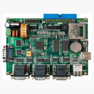 Transistors are a specific sort of swap. You possibly can identify them by their three terminals and their “D” form. Circuit boards often use Q to indicate transistor locations. Transistor diagrams are circles with three leads. Contained in the circle, one level goes directly to a bar, whereas the opposite leads branch off diagonally from the bar with considered one of them containing an arrow. Relays are electronic switches. Powered relays are open whereas disconnected relays are closed. These components typically have plastic shells with their specification written on them. Most boards use “K” to label relays. Transformers are usually fairly easy to identify by sight, and many have their specs printed on them. They are sometimes marked with an “T” on a circuit board. A swap is a element which controls the open-ness or closed-ness of an electric circuit. They allow management over present flow in a circuit (with out having to actually get in there and manually minimize or splice the wires). Switches are important elements in any circuit which requires consumer interaction or management. These variable resistors are usually marked in ohms utilizing three digits. The primary two digits are the numerous figures with the third proving the power of 10 multipliers. Potentiometers even have a letter code to point the resistance change, and a VR for variable resistor marked on them somewhere. These full circuits-on-a-chip will take some effort to identify correctly, as several various kinds of ICs can are available in the same bundle. Marked as U or IC on most circuit boards, you usually must search for the device’s datasheet to seek out the data. Datasheets supply a schematic of their gadgets. Are usually discovered on-line. Circuit diagrams use rectangular blocks to signify these components. Essentially loops of wire, inductors are sometimes difficult to determine. You can find them either as a uncooked wired coil or coloration coded. In both case, it is best to check the parts earlier than using them. Fortunately, PCBs use an L to point an inductor. In electronics and electrical engineering, a fuse is an electrical security device that operates to offer overcurrent protection of an electrical circuit. Its important element is a metallic wire or strip that melts when too much current flows by means of it, PCBA thereby interrupting the present. It’s a sacrificial system; once a fuse has operated it’s an open circuit, and it must be changed or rewired, depending on type. If you are you looking for more regarding pcba – http://Www.Authorstream.com, have a look at our own internet site. Diodes one-method electrical parts with a band that indicated the present course. You’ll find their specs on their shells. You may additionally come across LEDs. Zener diodes as well. Diagrams use an arrowhead and a bar to indicate diodes whereas circuit boards use D or CR. The arrow points in the route of the current. Marked on boards with an X or Y, these pure clocks keep our electronic devices working easily and on time. The unique appearance of a crystal oscillator makes these parts the best to establish. They even have their specification written on them. Capacitors store electric charge. These components come as small disk-formed gumdrops or massive cylinders. In either case, the knowledge is printed straight onto them. PCBs, use C to make capacitors. A Bridge rectifier is an Alternating Current (AC) to Direct Current (DC) converter that rectifies mains AC input to DC output. Bridge Rectifiers are widely utilized in power supplies that provide vital DC voltage for the digital parts or devices. They are often constructed with four or more diodes or another managed stable state switches. Depending on the load present requirements, a correct bridge rectifier is selected. Components’ ratings and specifications, breakdown voltage, temperature ranges, transient present score, forward present rating, mounting requirements and different issues are taken into account while choosing a rectifier energy provide for an appropriate digital circuit’s application. A LED, or PCBA mild emitting diode, is a component that can give off light. You will discover them in single and multi-color and low and high-power varieties. Low-energy, single colour LEDs are the most common. They often come in their respective colors, but not all the time. They may only have two terminals, a cathode, and an anode. Multi-coloration ones have multiple shade. A set of terminals for every coloration. High-power LED has a big steel casing to dissipate the extra heat. LEDs use the diode image on diagrams.


WELCOME TO MY WORLD